
- English
- Español
- Português
- русский
- Français
- 日本語
- Deutsch
- tiếng Việt
- Italiano
- Nederlands
- ภาษาไทย
- Polski
- 한국어
- Svenska
- magyar
- Malay
- বাংলা ভাষার
- Dansk
- Suomi
- हिन्दी
- Pilipino
- Türkçe
- Gaeilge
- العربية
- Indonesia
- Norsk
- تمل
- český
- ελληνικά
- український
- Javanese
- فارسی
- தமிழ்
- తెలుగు
- नेपाली
- Burmese
- български
- ລາວ
- Latine
- Қазақша
- Euskal
- Azərbaycan
- Slovenský jazyk
- Македонски
- Lietuvos
- Eesti Keel
- Română
- Slovenski
- मराठी
- Srpski језик

Why do PCBA electronic engineers always put two 0.1uF and 0.01uF capacitors in the circuit?
We need to understand why PCBA electronic engineers put two capacitors in the circuit. First, we need to understand the concepts of bypass and decoupling.
1. Bypass and decoupling
Bypass capacitor and decoupling capacitor are common concepts in circuits, but it is not easy to understand them.
To understand these two words, we have to go back to the English context.
Bypass means taking a shortcut in English, and it also means the same in the circuit, as shown in the figure below.
Couple means a pair in English, which is extended to pairing and coupling. If the signal in system A causes the signal in system B, then it is said that coupling occurs between A and B systems (Coupling), as shown in the figure below. And decoupling means to weaken this coupling.
1) Bypass
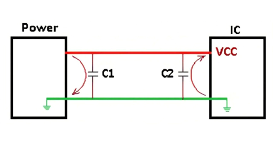
If the Power is interfered with, it is generally a high-frequency interference signal, which may cause the IC to not work properly.
Connect a capacitor C1 in parallel near Power, because the capacitor is open circuit to DC and has low resistance to AC.
The high-frequency interference signal flows back to the ground through C1, and the interference signal that would have passed through the IC takes a shortcut to GND through the capacitor. Here, C1 is the role of the bypass capacitor.
2) Decoupling
Since the operating frequency of the integrated circuit is generally high, when the IC starts or switches the operating frequency, a large current fluctuation will be generated on the power supply wire. This interference signal will directly feedback to the Power and cause it to fluctuate.
Connect a capacitor C2 in parallel near the VCC power supply port of the IC, because the capacitor has an energy storage function, it can provide instantaneous current to the IC and reduce the impact of IC current fluctuation interference on the Power. Here, C2 plays the role of a decoupling capacitor.
3. Why use two capacitors?
Back to the question mentioned at the beginning of this article, why use two capacitors of 0.1uF and 0.01uF?
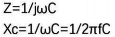
The calculation formulas for capacitor impedance and capacitive reactance are as follows:
2. Bypass and decoupling in the circuit
As shown in the figure below, the DC power supply Power supplies power to the chip IC, and two capacitors are incorporated into the circuit.
Capacitive reactance is inversely proportional to the frequency and capacitance value. The larger the capacitance and the higher the frequency, the smaller the capacitive reactance. It can be simply understood that the larger the capacitance, the better the filtering effect.
So with a 0.1uF capacitor bypass, isn't it a waste to add a 0.01uF capacitor?
In fact, for a specific capacitor, it is capacitive when the signal frequency is lower than its self-resonant frequency, and inductive when the signal frequency is higher than its self-resonant frequency.
When two capacitors of 0.1uF and 0.01uF are connected in parallel, it is equivalent to widening the filtering frequency range.
Send Inquiry
-
Delivery Service


-
Payment Options