- English
- Español
- Português
- русский
- Français
- 日本語
- Deutsch
- tiếng Việt
- Italiano
- Nederlands
- ภาษาไทย
- Polski
- 한국어
- Svenska
- magyar
- Malay
- বাংলা ভাষার
- Dansk
- Suomi
- हिन्दी
- Pilipino
- Türkçe
- Gaeilge
- العربية
- Indonesia
- Norsk
- تمل
- český
- ελληνικά
- український
- Javanese
- فارسی
- தமிழ்
- తెలుగు
- नेपाली
- Burmese
- български
- ລາວ
- Latine
- Қазақша
- Euskal
- Azərbaycan
- Slovenský jazyk
- Македонски
- Lietuvos
- Eesti Keel
- Română
- Slovenski
- मराठी
- Srpski језик
Fault analysis and troubleshooting in PCBA processing
In the process of PCBA (Printed Circuit Board Assembly) processing, fault analysis and troubleshooting are key links to ensure product quality and production efficiency. By systematically identifying and solving faults, product reliability can be improved and production costs can be reduced. This article will explore common fault types, analysis methods and troubleshooting strategies in PCBA processing to help companies improve production quality and efficiency.

Common fault types
1. soldering defects
soldering defects are the most common problems in PCBA processing, including cold soldering, cold soldering, solder bridges and missing solder joints. Cold soldering is manifested as poor contact of solder joints, resulting in unstable electrical signal transmission; solder bridges refer to solder flowing to areas that should not be connected, forming a short circuit; missing solder joints refer to solder joints that are not fully formed, resulting in open circuit problems.
2. Open circuit of circuit board
Open circuit problems refer to the fact that some lines or solder joints on the circuit board do not form a reliable electrical connection. Common causes include poor soldering, damaged PCB substrates and design errors.
3. Short circuit problems
Short circuit problems refer to the accidental contact of two or more circuit parts on the circuit board that should not be connected, resulting in abnormal current flow, which may damage the circuit board or components. Common causes include solder overflow, copper wire shorting, or accidental contact caused by contaminants.
Failure Analysis Method
1. Visual Inspection
Using a microscope or high-magnification camera for visual inspection can detect solder joint defects, open circuits, and short circuits. A detailed visual inspection of the circuit board can quickly identify obvious defects.
Check the solder joints: Observe the shape and connection status of the solder joints to confirm whether there is a false solder joint or cold solder joint.
Check the circuit: Check whether the circuit on the circuit board is intact and whether there is an open circuit or short circuit.
Implementation strategy: Perform visual inspections regularly, find and record problems, and take repair measures in time.
2. Electrical testing
Electrical testing includes functional testing, continuity testing, and insulation testing, which can detect the actual working status and electrical connection of the circuit board.
Functional testing: Perform functional testing after assembly to confirm whether the circuit board is working properly according to the design requirements.
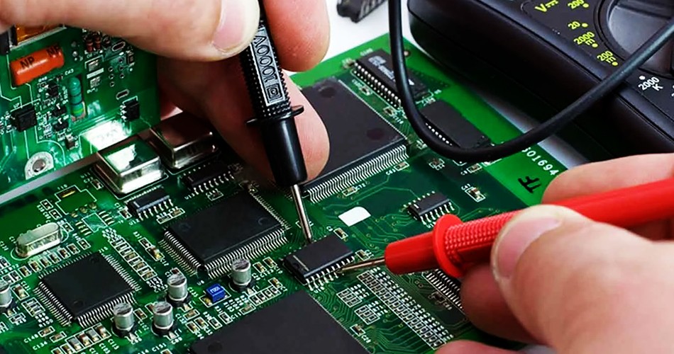
Continuity testing: Use a multimeter to test the various connection points of the circuit board to check whether there is an open circuit problem.
Insulation testing: Test the insulation performance of the circuit board to ensure that there is no accidental short circuit in various parts of the circuit board.
Implementation strategy: Conduct systematic electrical testing during and after production to detect and solve problems in a timely manner.
3. X-ray inspection
X-ray inspection is an effective method for detecting hidden defects, especially for detecting solder joint problems that are not easy to directly observe, such as BGA (Ball Grid Array).
Check solder joints: Check the soldering quality of BGA solder joints through X-ray inspection to confirm whether there are cold solder joints or solder bridges.
Detect internal structure: Check the internal structure of the PCB to identify possible short circuits or open circuits.
Implementation strategy: Configure X-ray inspection equipment to conduct regular and spot internal inspections to ensure soldering quality.
Troubleshooting strategy
1. Re-soldering
For soldering defects such as cold solder joints, cold solder joints, and missing solder joints, re-soldering is usually required for repair. Ensure the correctness of the soldering process and adjust the soldering parameters to obtain good soldering results.
Clean the surface: Clean the soldering surface before re-soldering to remove oxides and contaminants.
Adjust soldering parameters: Adjust the temperature, time, and solder amount according to the soldering requirements to ensure soldering quality.
Implementation strategy: For soldering defects, re-weld and check the solder joints to ensure that the soldering quality meets the standards.
2. Replace damaged parts
For problems caused by component damage, such as open circuits and short circuits, it is usually necessary to replace the damaged parts. Ensure that the replaced parts meet the design requirements and perform soldering.
Identify damaged parts: Identify damaged parts through electrical testing and visual inspection.
Replace: Replace damaged parts, and re-weld and perform functional testing.
Implementation strategy: Replace damaged parts and ensure that the quality of new parts meets the requirements.
3. Repair PCB substrate
For PCB substrate damage problems, such as cracks or interlayer peeling, PCB repair technologies such as circuit repair and substrate reinforcement can be used.
Repair circuits: Use conductive glue or conductive wire to repair damaged circuits.
Reinforce substrates: Reinforce the substrate to reduce the risk of physical damage.
Implementation strategy: Repair PCB substrates and ensure that the repaired substrates meet the use requirements.
Summary
In PCBA processing, fault analysis and troubleshooting are key links to ensure product quality. Through the identification of common fault types, systematic fault analysis methods and effective troubleshooting strategies, the yield rate of products can be improved and production costs can be reduced. Regular visual inspection, electrical testing and X-ray inspection can help improve production quality and corporate competitiveness by timely discovering and solving problems.
Send Inquiry
-
Delivery Service


-
Payment Options


